My Experience Printing Clear PETG
Using a Prusa MKS3+ and some clear Polymaker PETG, I'll walk through how I was able to print (pretty) clear using my 0.4mm nozzle and some settings that I haven't seen listed anywhere else.
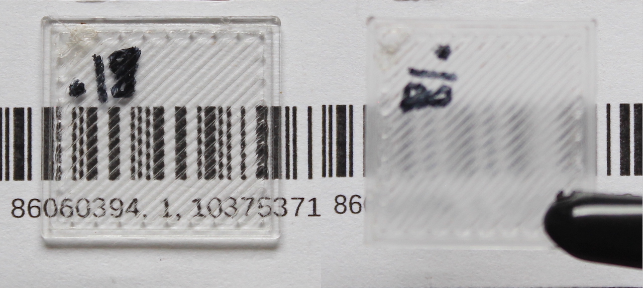
Left: v0.18 laying on paper, Right: v0.18 1.25cm above paper
And while I believe the settings that work for me aren't going to work for you, I'll do a quick demo of a small tool I'm developing that should speed up fine parameter tuning that is necessary when trying to achieve good results printing clear filament.
Note: These parameters require constant tuning with printer maintenance. During testing and writing this article, I changed the entire hot end in my Prusa MKS3+ which caused my live-z offset to change and almost every parameter I had tuned below no longer worked for me.
Knowns
A few parameters I've not taken a look at given everyone has recommended these settings:
-
cooling stays off - turn off cooling entirely since the fan will ruin the finish of the part, resulting it to come out cloudy
-
layer height at 0.1mm - I've only seen any guide suggest to print very small layer heights. I've not explored going smaller than 0.1mm and to be honest, I've not even tested 0.15mm or 0.2mm
-
infill perimeters overlap - this setting dictates how much overlap appears at the joint between infill and perimeter tracks. Originally I had thought this setting wasn't that important for the small square tests I was printing, but if you print a square and see that the shorter diagonal infill tracks are slightly over-extruded while the longest infill tracks are under-extruded, you might lower this setting since some of the overlap will be running into your infill track extrusion
-
infill = 100% aligned rectilinear - this setting might be the most obvious. Without 100% infill, you're going to get refraction inside the part, entirely ruining the transparency. Your tracks also need to be aligned because you will have lines between the extrusion tracks and stacking these lines maximizes the overall transparent area within the print.
Major Factors at Play
Infill Extrusion Width and Flow Percentage
I'm going to talk about these two parameters at the same time since only mentioning one would just leave out half of the story.
Extrusion width is the distance between the center of the extruded filament tracks. We look specifically at infill extrusion width, well, because the majority of our print is that 100% aligned rectilinear infill!
Our flow percentage is the amount of filament leaving the nozzle. Now, PrusaSlicer varies this in the gcode directly depending on the layer height you're printing at, so strictly defining what 100% means doesn't do much good and any meaning of this parameter should be a direct comparison of two results using different flow percentages.
We'd like to have the largest extrusion width possible. This eliminates the number of track lines we see on the final print and increases the amount of area that is just composed of clear infill - the exact reason our print appears clear.
Well, why can't we just crank the extrusion width up as high as possible? Well, our nozzle diameter will end up limiting us on this number. You see, as the extrusion width increases, the amount of filament we need to push out the end of the nozzle also increases as we need to fill more horizontal area with filament. Sometimes, though, we push out a little too much filament or not enough filament. The figures below demonstrate each of these scenarios and the overall effect on the layer surface. Effectively, the less even the top surface, the more we will end up seeing the impurities in the final print.
In Figure 1, not enough filament is squeezed out creating small gaps in between the tops of the layers. Alternatively, in Figure 2, we are extruding too much filament which starts to flow upward following the angled shape of the nozzle.
Figure 1: under extrusion
Figure 2: over extrusion
Temperature
Temperature directly controls how viscous our extruded filament is. When printing clear PETG, you'd like it to cleanly flow out of the nozzle and therefore you will print your filament at a higher temperature. Now, note that above we said that we aren't using any cooling fans. This can get a little tricky when you're trying to do more complicated maneuvers such as bridging and your filament is just too hot to bridge across. Your printer also might be pushing its limitations as well, as mine only prints as high as 295C before starting to complain.
Speed
The overall printing speed is going to allow us to place the filament more delicately onto the surface of the previous layer. Printing at a lower speed is recommended because it requires less overall pressure inside the hot end. This increases the overall time the filament stays in the hot end increasing the chances all of it gets completely heated to the correct temperature and gives us a bit more protection against air bubbles.
Another benefit of lower speed is that the nozzle's vicinity to the previous layer for a longer amount of time might give better bonding between the previous layer and the current layer that's being extruded. Now, I've not verified or researched this exact fact, so I'm just using my intuition when it comes to theories like this.
Results
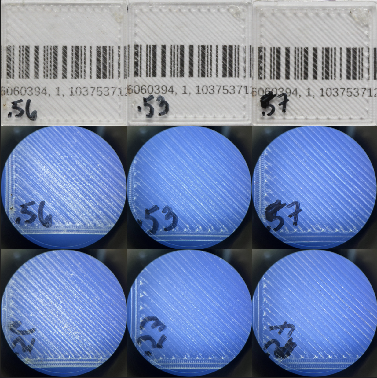
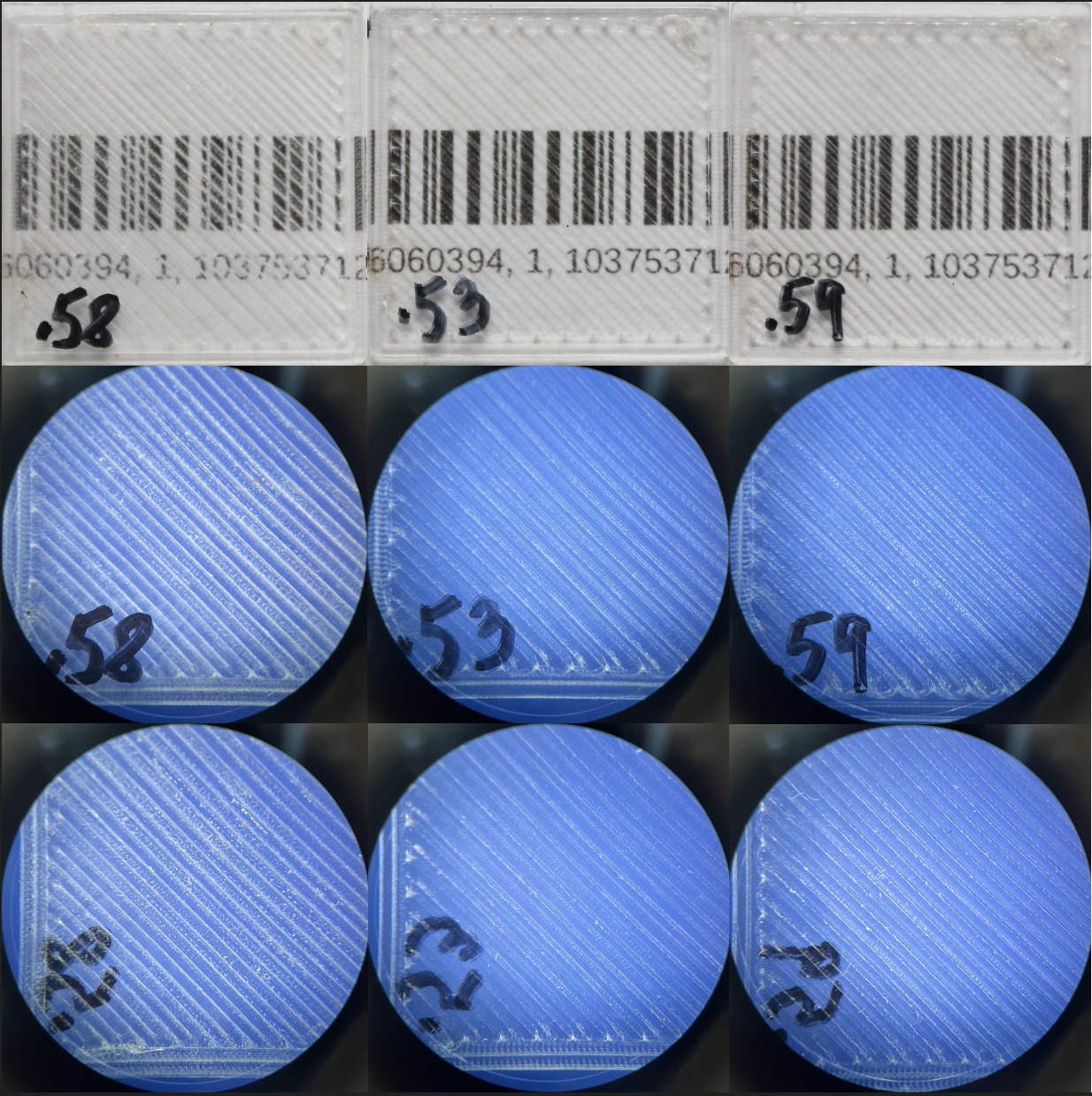
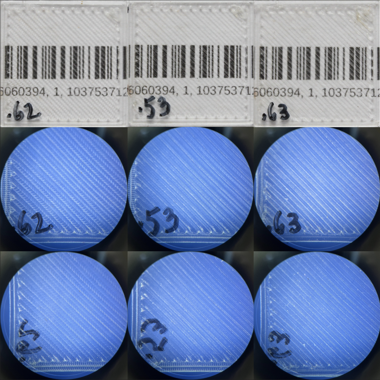
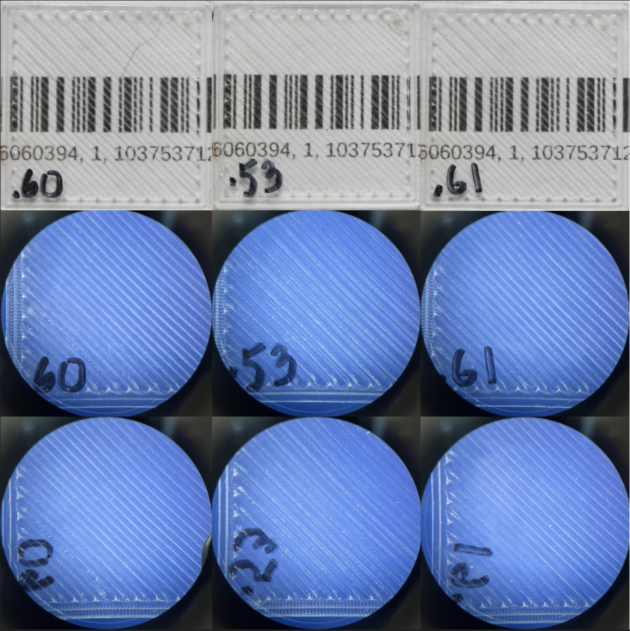
Given the above explanations of our knobs that we're turning, we can see the result each has on the overall print. The images below are all the same model: a 1mm thick 25x25mm square. The left, middle, and right columns will be prints containing a low, medium, and high value, respectively for the given parameter in the heading. The first row is the print laying directly on a barcode and the second and third rows are images of the bed layer and final layer of the print, respectively.
In my opinion, the best print I've been able to successfully reproduce has been v0.53 that you see in the following pictures. This mainly comes down to the lack of nozzle marks on the final print as well as more muted track lines as compared to some of the other prints. Ultimately, this may come down to a matter of opinion or even just an artistic decision on the use of the print e.g. how much detail should show through the print.
Extrusion Width
Flow Percentage
Temperature
Speed
Experimental methodology
The above parameters can be a bit hard to tune at the same time, since flow percentage and extrusion width are dependent, but the other two variables are independent. It's not 100% clear this is even the case, as you might get some weird under-extrusion happening when decreasing the temperature causing the flow percentage needing to be increased and tuned again.
Ideally I'd be able to specify print settings on multiple objects on the build plate and have those be printed using the settings for just that object. The layers would be intertwined and the printer would just switch between the setting configurations automatically per object allowing us to print several permutations of the above parameters at the same time.
Well, I believe you are able to do this with Simplify3d using something to the effect of object profiles (??), but I'm not willing to shell out the money to try this out, so I'll stick to trusty PrusaSlicer. It still allows you to select objects and select very basic setting changes between the models on the build plate, but nothing fancy like we want. We're in the territory of Advanced settings so of course it's not going to expose those parameters to us.
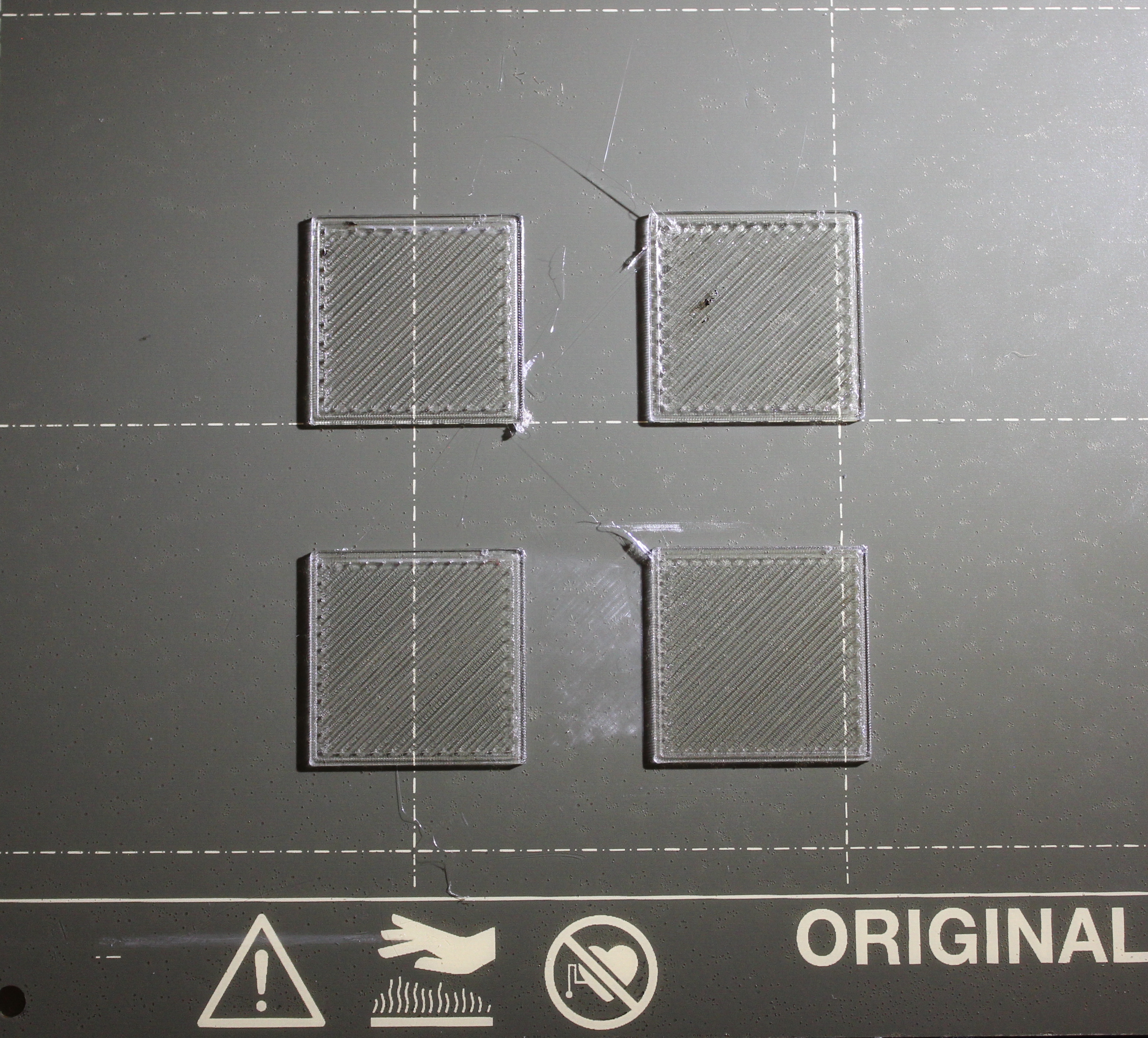
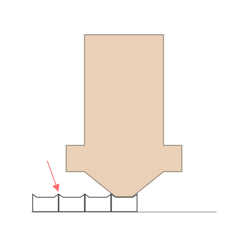
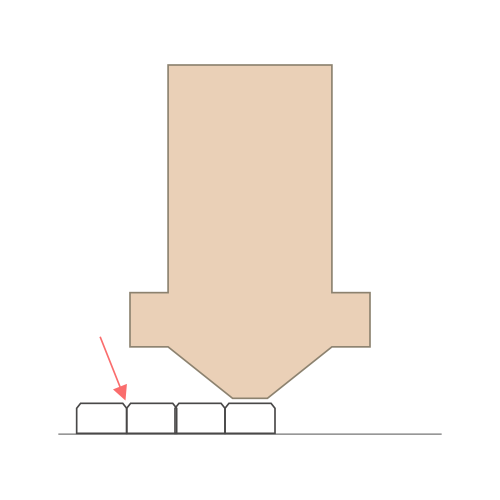
This is where the tool I mentioned above comes into the picture. I wrote a quick script that will generate a random permutation of the above parameters within given bounds. It will then generate a full PrusaSlicer configuration using the selected parameters joined to a base configuration and slice a base model N times with N unique configs. Then, we can split each .gcode file by layer and stitch the prints together such that each model is printed with the specific test settings we intend for just that model only. Interleaving multiple prints, as you would have it
The code is located in this github repository and I'll share some images of the experience below. I manually generated some parameters in order to clearly show that each object is printed with different settings (even though it might be a little hard since the lighting makes things hard to see).
Improvement Plans
It would be cool if this script evolved into an entire program that had a user friendly frontend. I also think this only works if the program has the ability to recognize a specific user's context which would allow them to rank the resulting print which would be used to generate even better settings for the next iteration of printing. Narrowing down the settings using a process like this would be insanely helpful as I've spent several days even just getting to the level you've seen in these pictures. If you have any suggestions or want to chip in, please feel free to open an issue in the git repository linked above!