


v0.1 & v0.2
3-24-2024
I've been practicing SMD soldering with a new optical microscope I just got, but the current soldering stand that I have has these ~12 inch flex arms that are truly too long for use with the microscope. The base is a steel powder-coated plate and due to the optics of the microscope, the item you're viewing can't be more than ~5-7 centimeters from the table that it's sitting on. I've been bending the flex arms horizontally (almost like a spiral pattern) in order to effectively lower the z-height of the part. Ideally, I'd have something that didn't need constant readjusting like the flexible arms, and since the base plate of the stand I already have is steel, I took the opportunity to whip something up myself.
Attempt 1
My first thought was to hold the board using a through-hole screw system. So you'd place your pcb on some stanchion-like support that might clamp the board by screwing it down. Each support is going to have a magnet on the bottom in order to make it not move on the steel plate, and since the magnets slide on the powder-coating, I'm going to glue a thin layer of a rubberized sheet (must've bought when sourcing parts for another project) to hold it still on the plate.
When I actually went to measure the holes in a PCB I had, I realized I had just imagined all the holes being there in the first place, so in order to keep my supports accessible to all boards, I went with a notched approach where the corner of a board could easily fit into the support. Most boards I'll work on are either 1.2mm or 1.6mm, so I just put two separate notches in each support post with a label next to them.
Here's a couple pictures from the .stl of my first attempt.
Attempt 2
Once I was able to print and test this out, I realized that the slots for the 1.2mm and 1.6mm boards was too small for the board to fit in. I had a 0.05mm tolerance (1.25mm), but I also was printing at 0.2mm, and the gap to bridge the slot was just too big and the first layer that formed the bridge just started to droop. I printed this with the top (faceted side) against the build plate (so, upside-down) so the gap to bridge was around 10mm.
Another change I wanted to make was the rubberized substance. I originally was putting down a full layer at the bottom, so there would be a 1.5mm rubber layer between the magnets and the steel plate. After popping some magnets into v0.1, I felt like I was going to need the extra magnetic strength coming from the magnets touching the steel directly, so I instead thought about cutting out a circle of the rubberized material and gluing it to the bottom, just like another magnet.
With these changes in mind, I increased the radius of the base cylinder in order to fit the extra circle on the bottom for the rubberized material, and I make the notches smaller so the gap to bridge would be significantly less (probably ~5-6mm now. I also decided to print at 0.15mm as well just to give myself any advantage against the loss of detail in slicing.
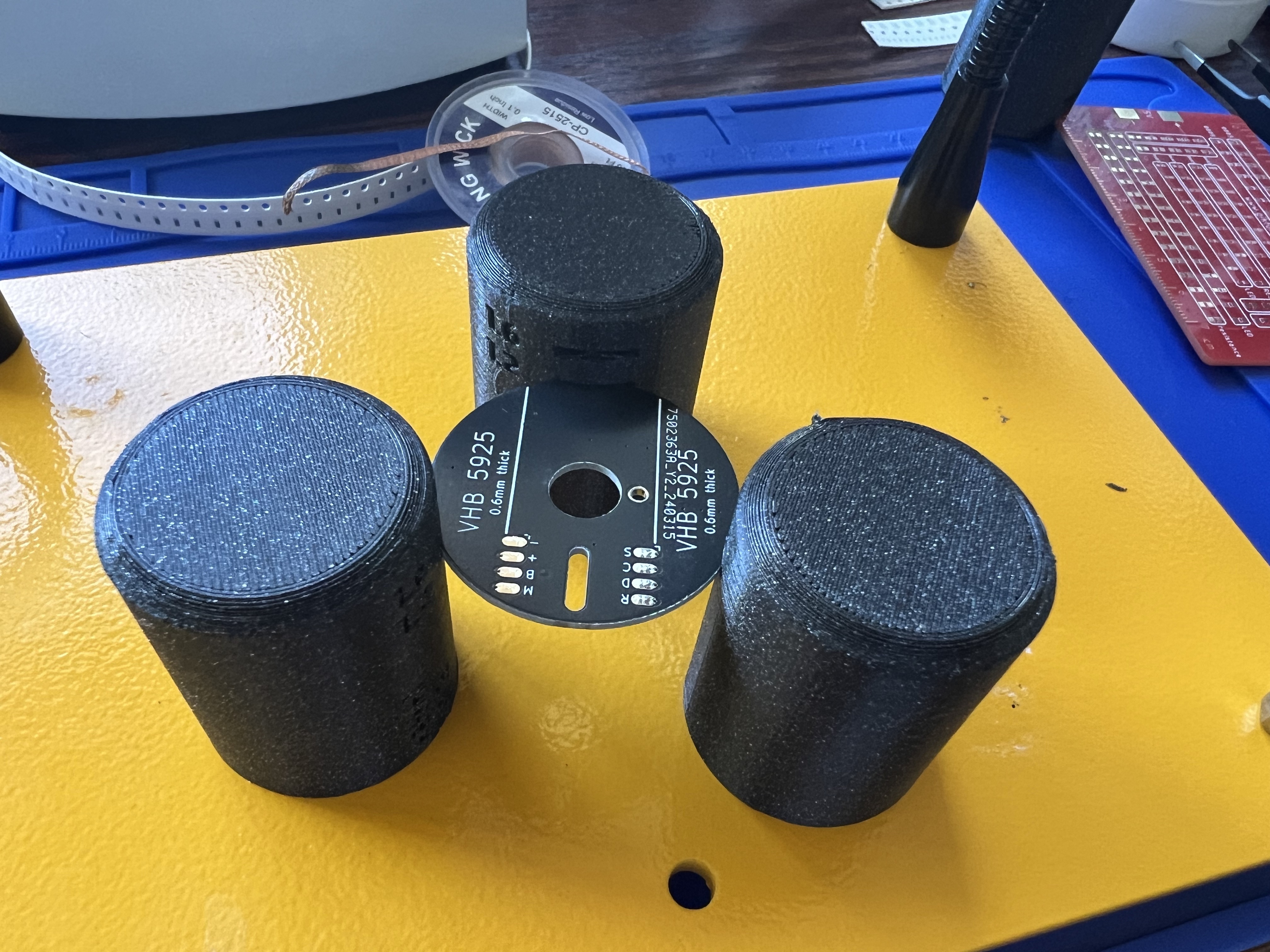
This one was a success! I was able to pop the magnets in and glue the rubber material to the center hole to get really nice adhesion to the steel plate.
Further Improvements
- multiple rubber pads - currently there's a single rubber pad in the center of the support. While it holds the support pretty well in regards to x/y translation, note that the rubber pad isn't big enough to prevent rotation of the support
- more supported board thicknesses