Introduction
4-29-2024
My Experience Building Scott Bezek's Smart Knob
I just finished building the Smart Knob, an open source gimbal motor-based knob graciously brought to us and maintained by Scott Bezek. I first stumbled upon this project while I was doing some research on keyboards/macropads related to my AWS Console Macropad Library.
Once I saw it I knew I had to build one. Mind you, I didn't even know what an ESP32 was at the time (roughly February). I also didn't have a great soldering setup. I had a $12 soldering iron from Amazon and some 2mm (or something like that) solder that I'd previously used to fasten some breadboard pins to a Pololu motor controller.
After spending a bit of money and my girlfriend buying me a dissecting scope (do recommend the 10x on this one) I was ready to tackle the project.
Steps
- Sourcing parts
- Print Parts
- Assembly
- Debugging
Sourcing Parts
This phase of the project was extremely easy, especially for a beginner. Now, not to say I'm a beginner to all electronics (I lasted 6 weeks in my undergrad electronics 1xx course before dropping), but I'm not too familiar with a lot of advanced electrical concepts.
Luckily you don't have to be. Scott has used an interactive BOM which shows the list of parts needed, where they go on the PCB, and where to source them via their corresponding part numbers. This was a game changer, as I certainly wouldn't have known the difference between a 0805 and 0603 component and mistakenly would have ordered them interchangably.
There are so many distinct parts needed (30 in fact) that I did forget a couple and had to unfortunately delay the build for one Digikey order. And while the most expensive part is the motor at ~$30, the next most expensive part is the Lilygo ESP32 module at $7 and the next being the motor controller at ~$2.5, so the overall cost for this build isn't terrible. I did order duplicates of every part, so I'd have to go back and actually calculate the overall cost of everything.
Another first for me was ordering the PCB boards. I actually ended up designing a board shortly after this project (you can check out the details on my wifi-thermometer project page), but again, the way that Scott presents the information really caters to beginners. All I needed to do was upload the .zip file on the github to JLCPCB, follow a few customization parameters that were clearly mentioned in the README, and in a couple weeks I had 5 main boards, 5 display boards, and a stencil.
Printed Parts
There are some printed parts required. These were relatively easy to print, although, I tend to have a battle with removing supports (I'm just lazy and haven't tuned that yet), so a couple parts required some good amounts of cleaning up.
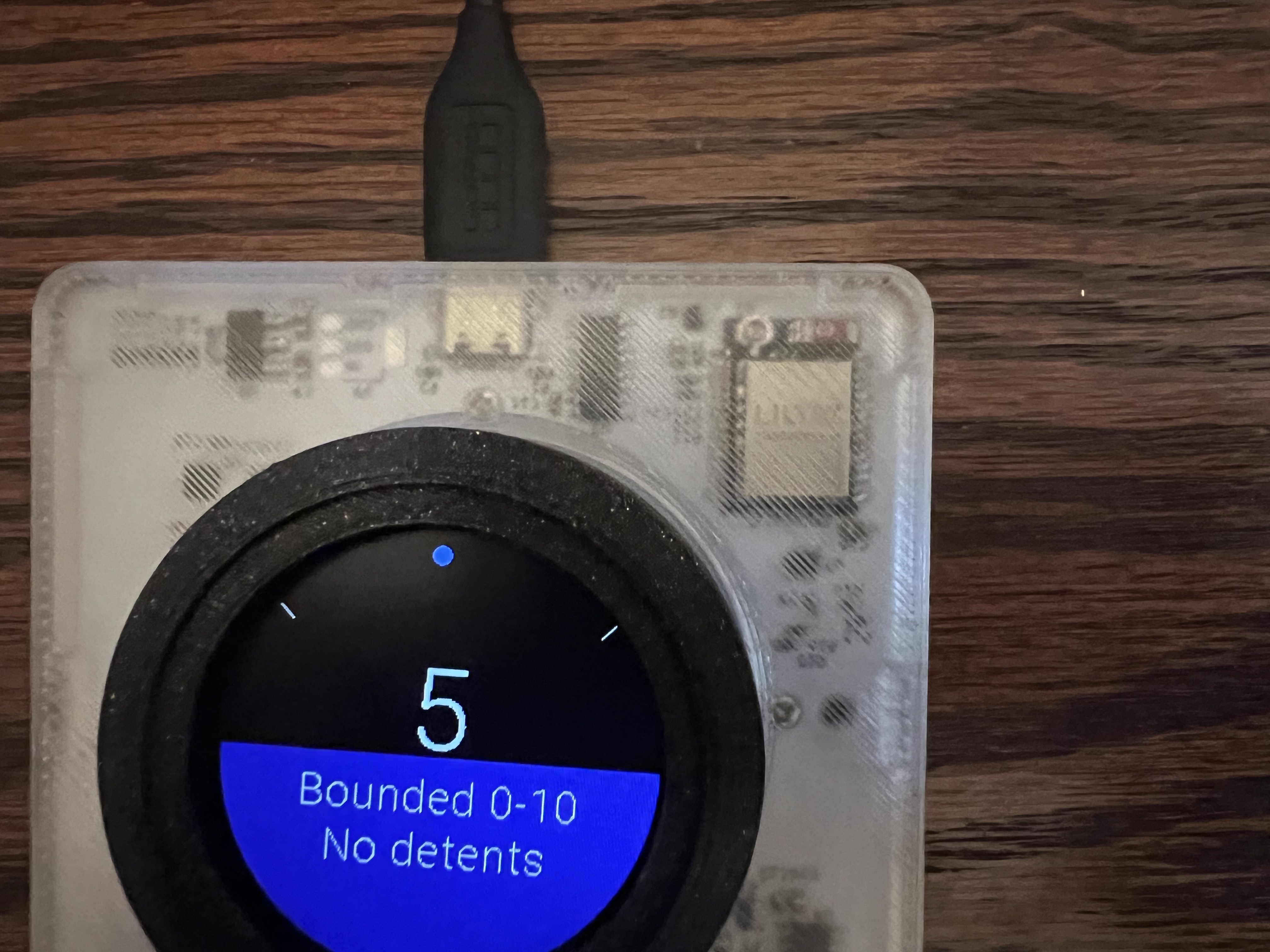
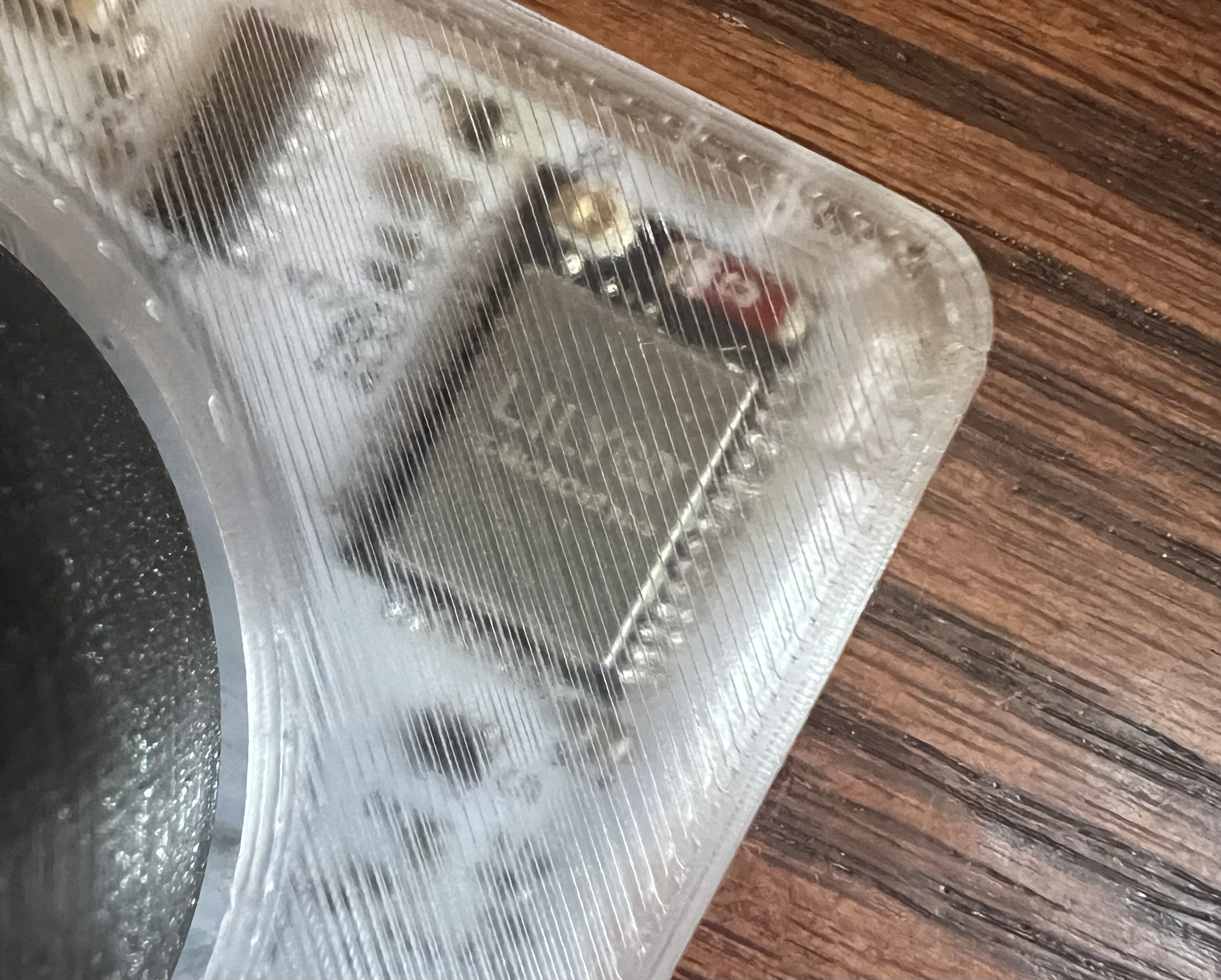
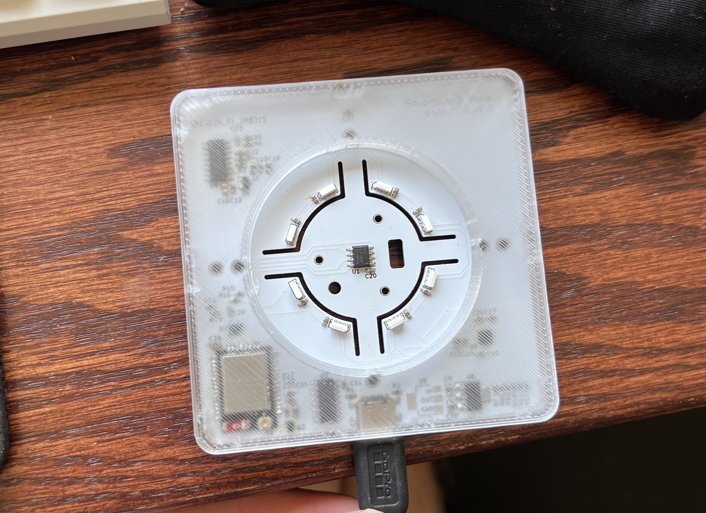
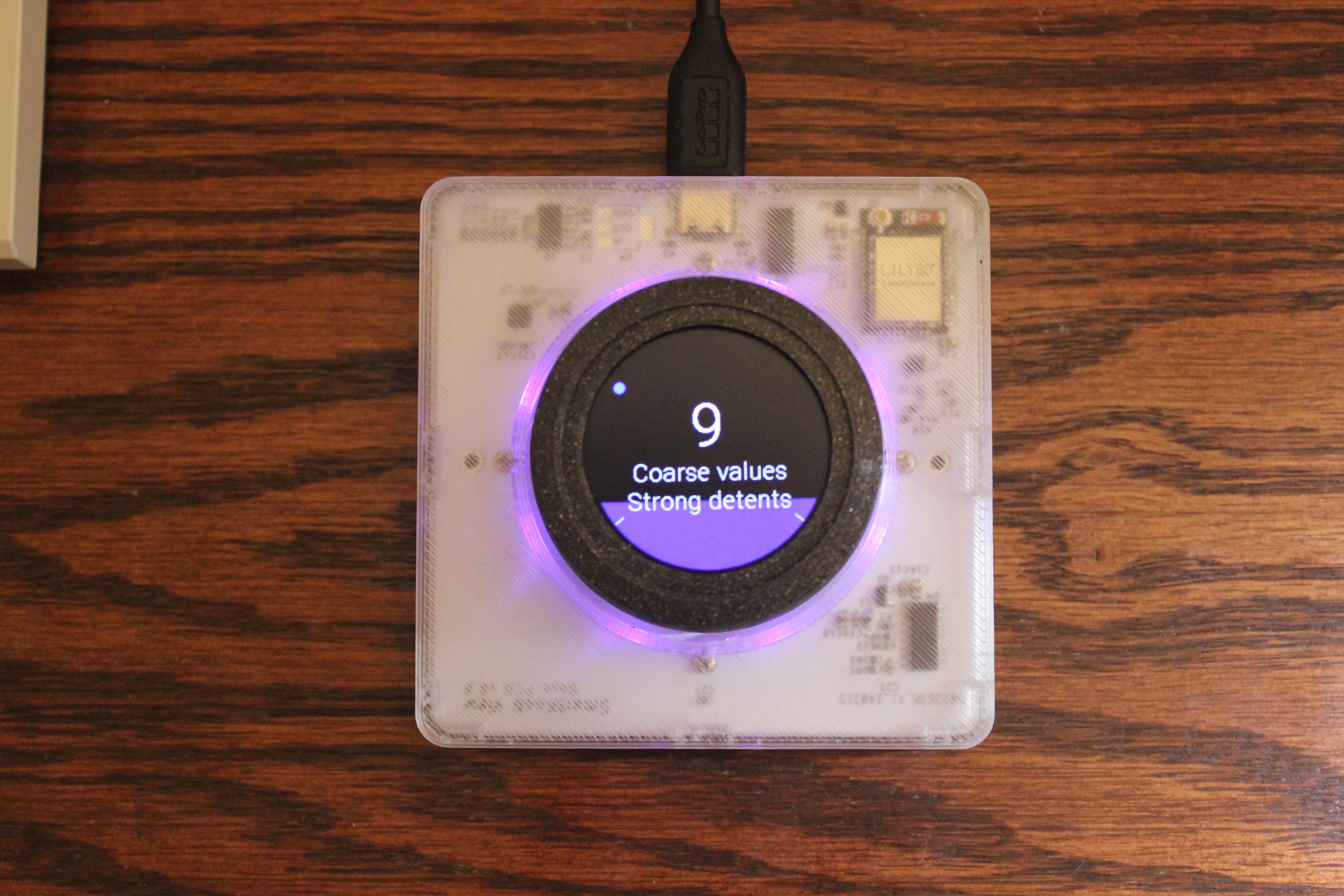
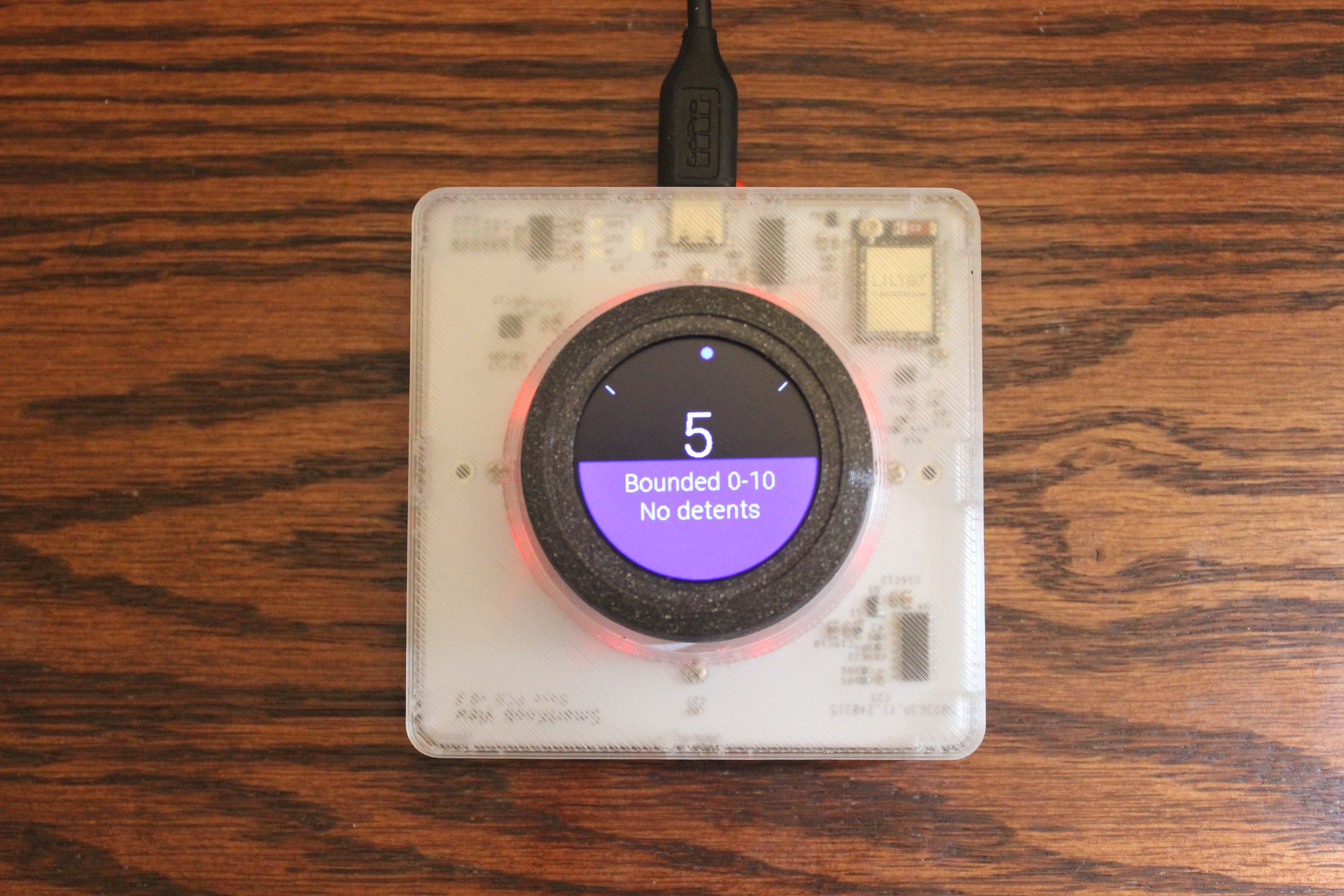
Originally I printed all parts in the Prusa Galaxy Black filament, but after soldering the board, I actually thought it would be cool to try and print in clear PETG. This spawned an entirely other post that is coming soon, but long story short, the clear case actually turned out perfectly. In the pictures it might seem a bit cloudy and fuzzy, and to some extent it is, but it really does pop and you can see more detail in person. I highly recommend checking out my article on how to print clear PETG so that you can also have a sick looking knob.
It's worth noting that if you're printing these components at home, it might be a good idea to print at 101% extrusion rate since both the snap-fit parts and the part locating keys can turn out a bit loose depending on your specific printer calibration. Also, your supports must be tuned well in order to get the right tolerances on the parts. The knob itself doesn't offer much wiggle room, so you're going to want prints that require very little cleanup.
Assembly
While I did order a stencil for the top side of the main PCB, I only actually used the stencil for the TMC6300 motor controller. This is specifically called out as one of the harder components to handle due to the bottom pad, but it's also an extremely small chip with 5 pins on each side. I ruined one motor controller and one PCB on my first attempt, but luckily was able to get a good result on my second.
Most of the components I just hand soldered, but a few of the other multi-pin chips I used solder paste. I had no issues with any of the components, but wish I had originally just hand soldered the ESP32 module since the closeness of the pads don't lend well to solder paste across the pins. Between betting the solder to flow and preventing bridging, it would be easier to just hand solder with 0.3mm solder.
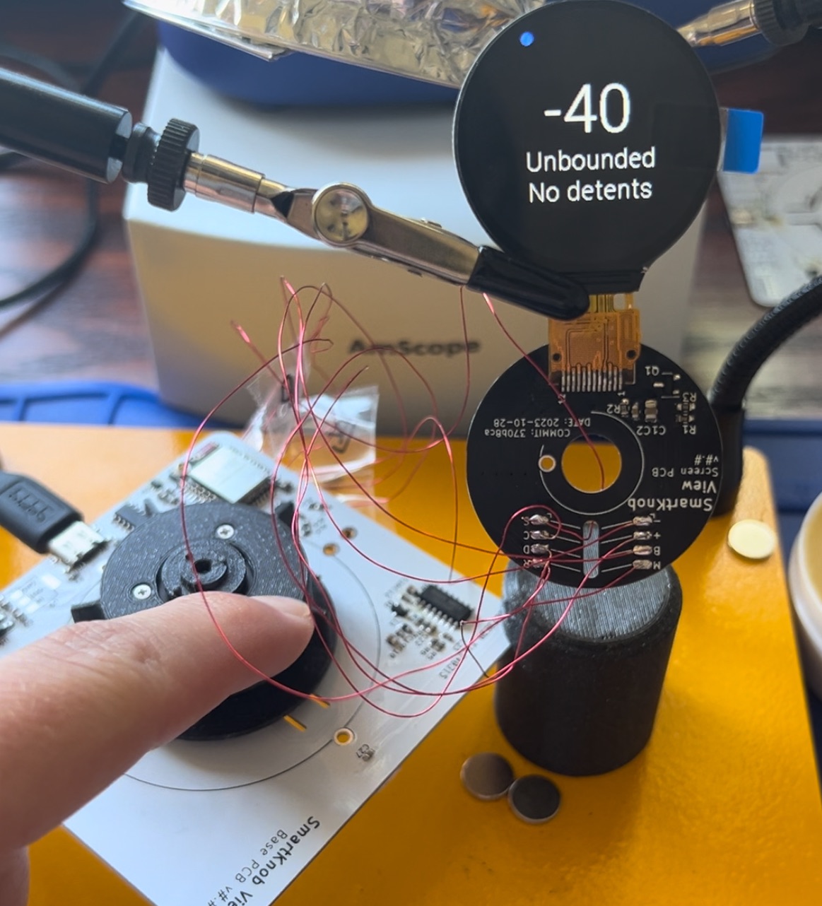
While I didn't have any issues wiring the LCD (I used 30 AWG enameled wrapping wire), it was time consuming and there is only one order you can assemble everything in so there was a bit of frustration as I had to disassemble everything a few times to get the parts I needed installed.
I had some issues keeping the LCD from moving, but ultimately the issue was that I had missed that I needed to buy 0.6mm VHB tape which takes the screen and adheres it to the screen PCB. This detail was a bit hidden in the README on the smartknob page, but after ordering and installing, everything fit perfectly.
Debugging
Immediately when I first plugged in the board, I was able to get platformIO to recognize the board, but the upload was failing. The first thing I did was half the default baud rate on everything and this ended up working well. I had the screen working and after calibrating the motor and strain resistors, I was able to go through the demo.
One thing I did find, though, was that you need to calibrate the LCD in the startup mode (unbounded no detents) as the boundedness may affect the final position of the motor if you calibrate in any of the other demo modes.
My only other issue was that the LEDs wouldn't work at all on my first assembly. I suspected that the first LED was just missing a connection because I couldn't get anything to light up. I desoldered one of the LEDs and hooked it up to another ESP32 dev board just to make sure I was understanding the FastLED library. This is when I found out that it's terribly hard to debug your LEDs if the very first one in the chain isn't sending the D_out signal on to the others. After a battle with the pad, I finally got a solid connection (although it still flickers at times) and we had light!
I titled this post as an introduction because I'm planning on doing a bit more with the Smart Knob, primarily trying to make it a bit dumber. But, I'll leave that for later in this thread.
Pictures