Psyche...
The last post was unfittingly titled Hardware Finalizations which might not have been the whole truth. I guess this is why you don't create your PCB before starting writing your firmware right...
Problems with Thermistors
Originally, the plan was to have a thermistor feeding an ADC port on the ESP32 which would convert the analog voltage from the thermistor into a resistance that could be again converted into a temperature by an equation created from parameters on the thermistor's datasheet.
A couple things I've learned: first, the ESP32 ADC apparently is not that great. At least, that's what I'm hearing because I've not tested this myself. Some sources state that the even when the voltage is safely inside the expected range an not towards one of the bounds that the error may be 100mv.
Second, measuring ambient air temperature also isn't very straightforward. Learning that a thermometer calibrated to 0.5 C is labeled as extremely accurate is quite surprising since most accurate measurement tools go down to the hundredths or thousandths of a unit. Also noted in this article are other factors such as air flow and properties of the housing that can make ambient temperature measurement more of a case-by-case problem to solve.
Our intended use case is indoors in a static location, but even then, the task of measuring the ambient air temperature will never be perfect. Even with a 0.1 C sensor, I'm willing to bet that in any room, there are 2 points which have an ambient temperature difference greater than 1C (would be something good to test..).
The second problem is pretty inherent to thermodynamics and measuring temperature in general, so I don't think we're going to deal with this outside of putting a few holes into our thermometer case. The first problem of the ADC error, however, is easily eliminated by delegating the task of converting the analog signal to a digital signal within the same chip.
After searching around, I was able to find the TMP117 low power digital temperature sensor which claims 0.1 C accuracy in the range of -20 C to 50 C. It is also I2C compatible, so we can read the signal directly with our ESP32 and there is no need for any more components other than a small capacitor tied to Vin and a few pull-up resistors on our I2C bus lines.
This chip works by constantly updating an internal register with the temperature reading at 1Hz (once per second). Using the I2C bus, we can read this register containing the temperature which is accurate down to something crazy like 0.07 C - accuracy we will never use. I connected the dev board I bought to our ESP32-PICO-D4 dev board and immediately we were reading the temperature! I did notice, though, that the temperature did seem to be ~1.5 C off of other cheap thermometers I had on-hand. To combat this, though, you can specify a constant offset in one of the chip's registers, but we'll focus on calibration at a later point.
Side Note: I did skip the slightly embarrassing part where I accidentally soldered the breadboard pins in upside-down and since I really wanted it facing up, I put everything on a hot plate, got the breadboard pins out, but managed to drop the board and have all the SMD components fall off. I then had to solder all the components back on. So much for buying a dev board so I didn't have to do the work myself :)
Real Life Test Bench
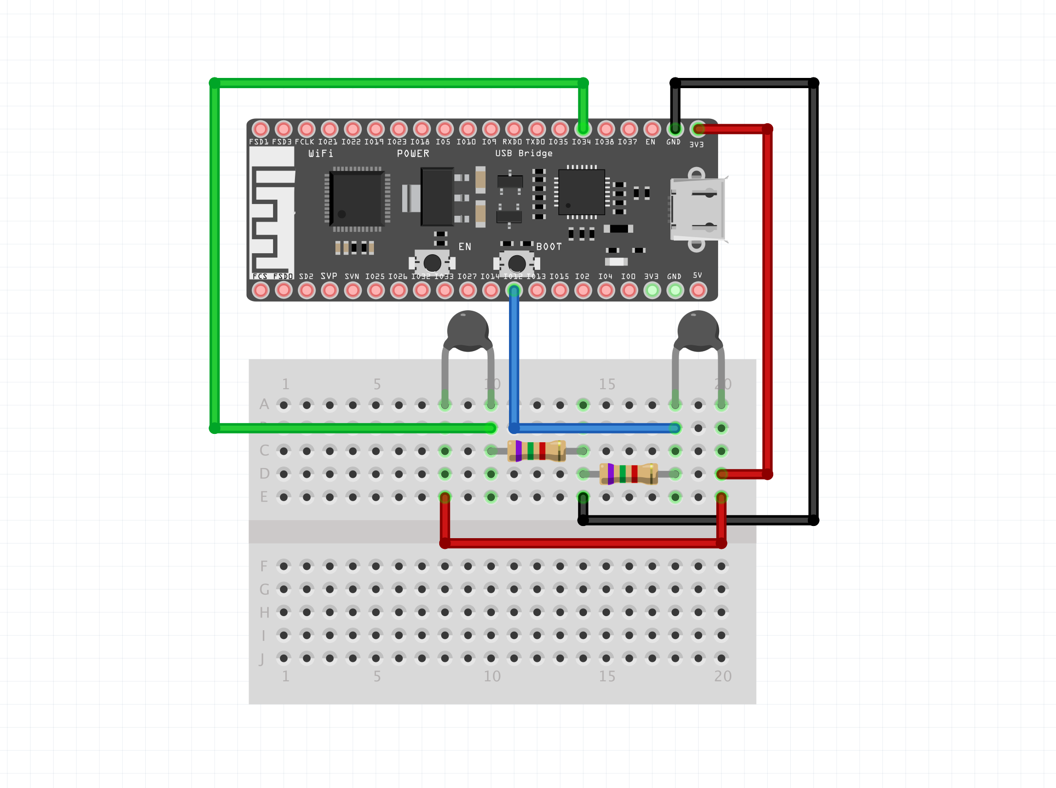
Now that I think (let's please hope, my wallet can't keep doing 2 digikey orders per week) I have all the components AND I've actually written test firmware for each component, I'm willing to share the current breadboard I'm using to start to piece the firmware together.
![[wifi-thermometer-breadboard.jpg]](/wifi-thermometer/v0.1-breadboard.jpg)
Working from left to right, we have:
- a simple breadboard push button (pull-up) - this is the primary input on the device itself
- TMP117 dev board - this board contains the digital chip introduced above that reads the ambient temperature
- RGB LED - the LED will be the only output interface on the device
- ESP32-PICO-D4 - our ESP32 development module. Note that we are going to be using the ESP32-C3-MINI-1 module, I just haven't had the time to switch the dev board.
Firmware Brain Block
I've been able to get example sketches working that interface with all the components you see here independently:
- I2C - this is the communication protocol used to interface the ESP32 with the TMP117
- pull-up button (with debounce)
- RGB LED
- Wifi AP
- Wifi STA
- ESP32 Deep Sleep
Even though all the components have been individually POC'd, I've got a bit of brain block on how to actually stitch them together. This is the first time I'm ever writing hardware, so the best practices and implications of choosing specific design elements still aren't completely clear to me.
It's also apparent that I'm going to need to have OTA firmware updates since I'm not planning on
Proposed approach
Here's the proposed approach. I'll have 4 tasks that can run:
-
Button Press Task - this task handles when we press a button. There are two types of button presses we register:
- Short button presses - these will be treated as some sort of status button. A short press will cause the RGB LED to produce a series of colors which can be diagnosed using a lookup table.
- Long button presses - these bring the unit into pairing mode. The pairing sequence is detailed below.
The button press task was largely code copied into the project from this git repository which includes functionality to handle debouncing the button presses.
This task will be created from boot and will never be deleted. Upon a short or long button press, a task for the corresponding functionality will be created (status or pairing task).
-
Status Task - this task will report the current state of a firmware defined error register to the user through the RGB LED located on the board. All other tasks will be able to write to this register (which will probably be represented as a 32-bit location) and this task will convert the bits to a color code that is presented to a user.
This task is self-deleting once it completes.
-
Pairing Task - this task allows a device to retrieve a wifi ssid and password which it can then use to connect to the network. For v0.1, this will be the only way that a non-network connected device may communicate with any other device.
As stated above, the button task drives when the pairing sequence is enabled. However, by default, if there is no network ssid or password stored on the ESP32, then pairing mode is automatically entered.
This task will delete itself once completed.
-
Configuration Task - this task handles updates to the device configuration. This may include adjusting parameters such as:
- interval between temperature readings
- temperature offset
- firmware update
As of v0.1, the only way to enter this task is from the POST response of the Temperature Read task which we are repurposing to push any updates down to the device.
This will be started by the main Temperature Read Loop Task if the response from the POST request is anything other than a simple OK since this response object will contain any changes that the user has made on their phone app. We'll be mindful here to try and decouple the configuration changes from the POST response.
-
Temperature Read Loop Task - this task initiates the I2C connection between the ESP32 and the TMP117 temperature sensor, reads the chip's temperature register, and connects to the wifi in order to send a POST request to a remote server containing the temperature telemetry.
This task won't even need a loop since we are deep sleeping at the end of it. It will be interesting to see the effect of the deep sleep on any other continuous task (i.e. button).
v0.1 Hardware Finalizations
Battery
From the last article, it was clear I'd be exploring using a 1.5V cell to power everything. While I'm keen to try that out in the future, the goal of using the 1.5V cell was for compatibility reasons (everyone has a AA battery at home), but the workaround of stepping that voltage up to 3.3V for the ESP32 was turning out to be a pretty big hassle. And while the wifi thermometer project is power sipping at most, some other future projects relating to this thermometer would require more power reserves, so I began to rethink the idea of putting a 1.5V cell in my design.
If all we're going for is compatibility, a simple 18650 lithium 3.7V cell would achieve the same thing. The most popular lithium battery form-factor. They're very cheap, easy to access, and there are chargers for these batteries which are also easily accessible. This means that I can move away from the boost converter I shared in the last post and instead move my focus to a LDO voltage regulator. I just built the Smart Knob which used this 3.3V LDO regulator which supplies power to the ESP32, which would work perfectly for my needs.
Additionally, my boost converter PCBs have been stuck in customs for over a week, so I'm not that sad about abandoning the other boost chip.
Button
On the thermometer, there does need to be some sort of input device present. I've not gone into too much detail about the UX or firmware design, but it will essentially work just like every other 2.4GHz wifi-enabled device. You'll connect it to your phone via bluetooth, send over the wifi credentials, then you can disconnect the bluetooth and start sending data via HTTP calls.
To initiate the bluetooth pairing sequence, there needs to be some sort of input device on the thermometer itself, so I added a single button which will control this process. There may be other use cases in the future that require some sort of input in order to complete the product UX, but with this one button we can be resourceful and use it for multiple purposes.
LED
Along the lines of adding an input mechanism to the device, a single LED mounted on the PCB should suffice for an output. I've not decided on whether this will be an RGB LED or just a single color, but both would work in this case. RGB would allow for color-driven outputs while the same could be achieved with a single LED and using multiple pulses.
Initial PCB Design
Here is the initial PCB design. It's still missing some important parts (+/- power pads), but I'm working to finalize those and will send this off for fabrication soon!
Unrealistic Scope?
Initially I wanted this device to have a built-in LiPo battery and a USB-c connector that would charge that battery. After doing some research, the necessary circuitry needed to charge a LiPo safely is a bit beyond the scope of my capabilities (and realistically what I wanted to learn with this project), so while I'd still like to use a LiPo for energy density purposes, It will be most likely a AA-sized rechargeable battery. This should eliminate the need to have any LiPo charging circuitry, but does introduce another issue.
1.5v ➝ 3.3v
The ESP32 that I'm planning to use is powered by 3.3v. I could just use a LiPo AA-sized battery which has a 3.7v charged voltage, but those aren't very common and you still need a special charger as most rechargeable lithium consumer batteries still operate at 1.5V.
We'll build this for the masses, however, this does mean that we need to convert the 1.5 volts from the battery into 3.3 volts and we'll do this using a boost converter. It's not extremely common to convert 1.5v to 3.3v since most would just use another battery to get the voltage up to ~3.0v which the ESP32 can accept. But, what's the fun in that?
In all seriousness, there are a few drawbacks of using a boost converter at 1.5v, namely the efficiency which will start to drop off at around that voltage. I found a chip that I wanted to use, the Texas Instruments TPS61022 which is an ultra-low-voltage input switching converter which should work fine for my purposes. Here's the efficiency graph of that chip at various voltages. I'm no expert at reading these graphs, but I believe we'll be around 90% (unless it's 90% for 1.8v input and a further 90% for a 3.3v output which would put us at ~80%):
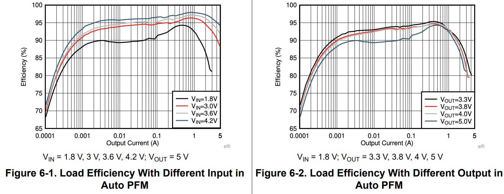
For now, I'm ok with that efficiency. It's not ideal and when the ESP32 is in deep sleep, we're going to be even less efficient as the ESP32 is stated to draw only 20 micro amps in that state.
Experimenting with the TPS61022
I'd really like to try this out and profile the chip before committing to it, but the issue is that this chip might be one of the smallest ICs I've worked with so far. It's on par with the TMC6300 motor driver that I used on the Smart Knob and I had a bit of trouble getting that soldered. I didn't really look too closely at the specs so I sort of thought I could just solder some 30AWG wire directly to the pads, but there are two reasons why that won't work:
- the chip is just too small
- in the datasheet, it states that there needs to be a capacitor within a few millimeters of the
VoutandGNDpads so any external wiring would probably be a waste of time.
My First PCB
How did I solve these issues? Well, by learning an entirely new skillset and making everything much more complicated!
I'd been wanting to design a PCB and I honestly thought the first version of the thermometer would be the first introduction I'd have to this. However, I'll bump up learning this in order to properly test one of the chips I'm considering for the final design (of the initial version, that is).
I'm using KiCad since it seems to be the most popular open-source PCB/schematci design software out there. The only purpose of this PCB is to test this chip, so I used a schematic pulled directly from the TPS61022 datasheet:
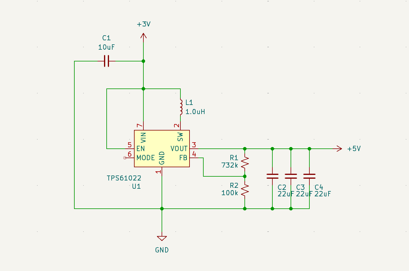
This resulted in a 2-layer PCB looking something like this:
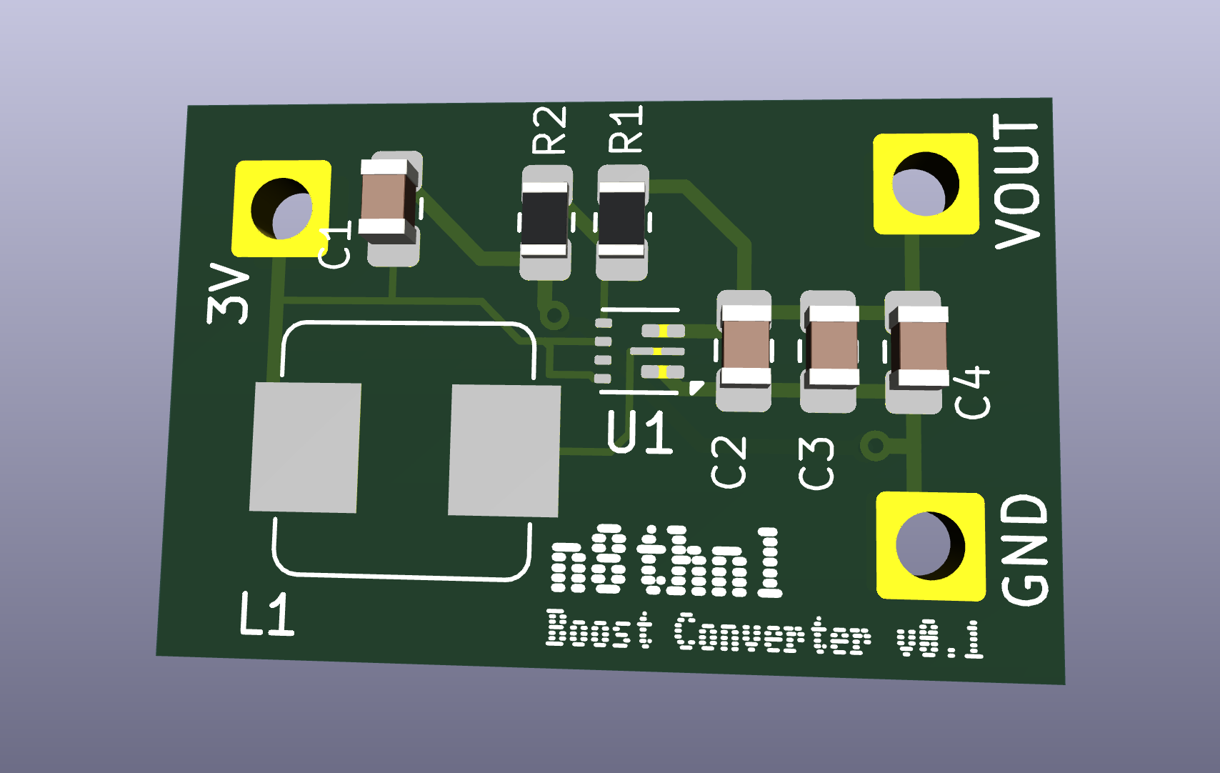
I send that over to JLCPCB and $17 later, it's currently in production and I should have it in my hands in a couple weeks.
ESP32 firmware
Along with any power considerations, I've also been playing with the ESP32 firmware. While before I was working in the Arduino IDE, I switched over to using ESP-IDF in vscode in order to have more configurability in the future when I actually implement the deep sleep and the network request to send the data.
I was able to get the deep sleep working (it's literally 2 lines of code), and I also had working examples of HTTP and UDP requests, so I'll work on getting the firmware finalized for an initial version.
What's Next?
Once I get the PCB in, I can see if this boost converter chip is indeed going to work. If so, I can build out a first version on the breadboard once the firmware is written as well.
Testing some Hardware
4-15-2024
The biggest design choice in this project is going to be the microcontroller and wifi transmission components. Originally, since I'm a PIC fan I was going to use one of the PIC chips with an ADC (something like a PIC16Fxxx), but since I've been living under a rock, I was able to stumble upon the ESP32, an up-and-coming microcontroller not many people are talking about \s.
I ordered a few thermistors from Digikey and wanted to set up a barebones temperature reading circuit to dip my feet in the water. One was a PTC thermistor, and to be honest, I haven't even touched that one. The reason being that the other two are 10k NTC thermistors which seem to be much nicer to work with (math-wise). Don't quote me on that, though.
The two 10k thermistors I'll be trying out:
The prices of these thermistors are in the $0.50-$0.90 range, and using an SMD thermistor will cost significantly less ($0.10), but I'm really digging the look of the glass thermistor. I think that making it a part of the design in general would make it a bit unique as well. We'll park that, though.
I'm wanting to see the characteristics of each and ultimately which type of thermistor would be more conducive to an ambient temperature sensor. The factors I'm looking for are:
-
accuracy
-
stability
-
consistency
Unfortunately, we're not going to be able to capture an accuracy metric or do any calibration to these thermistors since the reference thermometers I'm finding online are ~$200 USD which really goes against the budget project mindset.
The Circuit
The test circuit is extremely simple, I've got 2 voltage dividers where we can test the resistance of each thermistor. I chose a 7500k resistor for each since the resistance of the thermistor is likely going to be around the 9k-11k ohm range. Originally I had this circuit running on an Arduino and the ADC resolution forced me to use a larger and larger resistor to register any change in voltage. I could probably bump this up to a 10k+ resistor, so I'll put that as a next step. These two dividers are fed into two separate ADC inputs on my ESP32 dev board.
Once we have the voltage, we can easily find the resistance by using the voltage divider equation solving for R2:
R2 = R1 * (Vin / Vout - 1)Once we have the resistance, we need the specific B-constant for each thermistor. This will be in each datasheet. For our glass thermistor, this is 3892K and our bead thermistor is 3380K . The resistance along with the B-constants are then fed into this formula:
temp_kelvin = B / (ln(resistance / 10000.0 * exp(-1 * B / (273.15 + 25))))Ok, let's break this down. The resistance/temperature relationship that these 10k NTC thermistors have is an inverse logarithmic curve. The 10000.0 constant along with the 273.15 + 25 state that the resistance of this NTC thermistor is 298.15K (kelvin) at a 10k reference resistance. These two values are the axis references. Note that the output temperature is in Kelvin, so we do need to clean that up for a more readable output.
Code
const int ADC_PIN_GLASS = 34;
const int ADC_PIN_BEAD = 12;

float KNOWN_RESISTANCE = 7500;
float TEMP_REFERENCE = 25 + 273.15;

int B_GLASS = 3892;
int B_BEAD = 3380;

int global_count = 0;

float v_at_analog_pin(int pin_num) {
  int raw = analogRead(pin_num);
  return raw * (3.3 / 4095.0);
}

float find_unknown_R_given_drop(float voltage_drop, int known_resistance) {
  return known_resistance * (3.3 / voltage_drop - 1);
}

float temp_K_from_R_10k(int B, float resistance) {
  return B / (log(resistance / (10000.0 * exp(-1 * B / TEMP_REFERENCE))));
}

float temp_K_to_C(float temp_K) {
  return temp_K - 273.15;
}

float temp_C_to_F(float temp_C) {
  return (temp_C * 9 / 5) + 32;
}

void setup() {
  // put your setup code here, to run once:
  Serial.begin(115200);
  delay(1000);
}

void loop() {
  // put your main code here, to run repeatedly:
  float v_glass = v_at_analog_pin(ADC_PIN_GLASS);
  float v_bead  = v_at_analog_pin(ADC_PIN_BEAD);

  // Serial.println("v_glass: " + String(v_glass));
  // Serial.println("v_bead: " + String(v_bead));

  float r_glass = find_unknown_R_given_drop(v_glass, KNOWN_RESISTANCE);
  float r_bead  = find_unknown_R_given_drop(v_bead,  KNOWN_RESISTANCE);

  // Serial.println("r_glass: " + String(r_glass));
  // Serial.println("r_bead: " + String(r_bead));

  float temp_C_glass = temp_K_to_C(temp_K_from_R_10k(B_GLASS, r_glass));
  float temp_C_bead  = temp_K_to_C(temp_K_from_R_10k(B_BEAD,  r_bead));

  float temp_F_glass = temp_C_to_F(temp_C_glass);
  float temp_F_bead  = temp_C_to_F(temp_C_bead);

  Serial.println("glass temp F: " + String(temp_F_glass));
  Serial.println("bead temp F: " + String(temp_F_bead));
  Serial.println("");

  delay(500);
}
Output
The above code run on the ESP32 as shown produces the following output:
This was just maybe 12 or so seconds of the output, but it seems that the signal from the glass thermistor was much less corrupted by noise. The bead was weirdly 2-3 degrees lower than the glass thermistor and when I checked with an infrared thermometer, the temperature that it read was almost dead on the glass thermistor. This makes me believe maybe I'm missing something with the bead thermistor, but it's a 10k thermistor just like the glass one and the B-constant I pulled was the 25/50 just as it was for the glass thermistor.
Next steps:
- Get my hands on an SMD thermistor to test that against the glass
- Try with different resistor values
- Research charging circuits and batteries
- actually charge a battery
Project Introduction
4-10-2024
I was watching a Youtube short explaining thermistors (yes, that's pretty on-brand for my algorithm) and immediately thought of my dad. Hear me out... when they travel, my dad doesn't trust their ancient furnace, so he puts a wifi temperature sensor that we bought on Amazon in one of the rooms.
It ended up costing something like $40, though, and since I'm looking for a small project for learning overall E2E electronic component manufacturing (essentially what goes into productionizing a design), I think this will be a good, quick project that will teach me the following things:
- PCB design
- Thermistors
- More experience reading datasheets
- Introduction to ESP32 Microcontrollers
- Battery implementation (charge controllers, battery choice, etc)
To start off, I need to try and identify the thermistors I currently have laying around and try to get an accurate temperature using just an Arduino.
Oh, and I forgot to mention, if this project costs more than $10 USD to build, I will consider this a failure.